Hurricane Resilient Design Trends for Florida

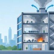
A hurricane does not need to cause a total structural failure to create a major property loss. Water intrusion through a failed roof edge, an unsecured rooftop unit, a flooded electrical room, or a damaged exterior door can take a multifamily, hospitality, retail, or commercial building out of service for weeks. Hurricane resilient design trends are therefore moving beyond minimum wind resistance. Owners are increasingly focused on keeping critical building systems operating, limiting water damage, and documenting decisions that support safety, insurance recovery, and long-term asset value.

For Florida property owners, boards, developers, and facility managers, the right approach is not to apply every available hardening measure. It is to identify the components most likely to interrupt occupancy or operations, then make code-compliant improvements with a clear return on risk reduction.

Hurricane Resilient Design Trends That Matter

The strongest trend is performance-based decision-making. A code-compliant building may satisfy the applicable minimum requirements, but minimum compliance does not always reflect an owner’s tolerance for downtime, repair costs, tenant disruption, or business interruption. A condominium with residents who rely on elevators, domestic water pressure, fire alarm systems, and conditioned common areas has different resilience priorities than an unoccupied warehouse.

This distinction is shaping project scopes. Rather than treating resilience as a single structural upgrade, owners are evaluating the building as a connected system: roof, exterior envelope, drainage, electrical distribution, mechanical equipment, plumbing, fire protection, communications, and emergency access. One weak link can limit the value of every other improvement.

Building envelopes designed to manage water, not just wind

Impact-rated windows, doors, shutters, and glazing systems remain central to hurricane protection. The more significant shift is the attention being paid to interfaces. The connection between a window and the surrounding wall, the sealant joint, flashing, door threshold, parapet cap, and roof-to-wall transition often determines whether wind-driven rain reaches interior finishes and concealed framing.

For renovations, replacement windows or doors should not be selected on appearance or product approval alone. The installation condition must match the approved assembly, wall construction, design pressures, and required anchorage. Field verification during construction is as important as specifying the right product.

Roofing work is receiving similar scrutiny. Current resilient roof designs focus on uplift resistance, edge securement, drainage paths, flashing continuity, and careful detailing around penetrations. Roof-mounted equipment, screens, solar components, and conduit supports must also be evaluated as part of the system. A new roof membrane cannot deliver its intended performance if adjacent components become windborne debris or create avoidable leak paths.

Elevated and protected MEP systems

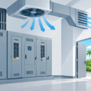
Electrical and mechanical failures frequently extend recovery after a storm. As a result, another major hurricane resilient design trend is relocating or protecting essential MEP equipment. Electrical switchgear, transformers, emergency generators, fire pump controllers, domestic water equipment, and communications infrastructure may require elevation above anticipated flood exposure, flood-resistant enclosures, or a different location within the building.

There are practical limits. Moving existing electrical service or generator equipment can trigger substantial utility coordination, structural modifications, shutdown planning, and permit review. In some buildings, the better investment is not full relocation, but targeted protection such as rated barriers, improved drainage, raised housekeeping pads, sealed penetrations, or revised equipment supports.

Mechanical systems deserve the same review. Rooftop units need engineered anchorage for applicable wind loads, while ground-level condensers and equipment need a flood strategy. Equipment elevation is useful only when refrigerant piping, electrical feeders, disconnects, controls, and service access are also addressed. Resilience is lost when a protected unit cannot be safely energized or maintained after the storm.

Power continuity with realistic load planning

Backup power planning is becoming more disciplined. Instead of assuming a generator must operate an entire property, owners are defining essential loads: life safety systems, emergency lighting, fire alarm, fire pump equipment where applicable, select elevators, domestic water pumps, communications, security, refrigeration, or a limited cooling area.

This approach can reduce capital cost while preserving the functions that matter most during and after an event. It also requires accurate electrical load calculations, selective coordination where needed, fuel planning, transfer equipment, ventilation, clearances, and maintainable access. A generator that is undersized, improperly connected, inaccessible after flooding, or unable to support its intended loads does not provide meaningful continuity.

Battery energy storage and solar generation are receiving more attention, especially for facilities seeking longer-term operating flexibility. These systems can support resilience, but they are not automatic emergency-power solutions. Their value depends on system configuration, islanding capability, critical-load panels, equipment location, fire protection considerations, and compliance with electrical and life-safety requirements.

The Design Trend Behind the Trend: Maintainability

A hardened building still needs to be inspected, tested, repaired, and operated under difficult conditions. That is why maintainability is becoming a defining part of resilient design. Equipment platforms need safe access. Roof drainage needs a path that can be cleared. Emergency systems need testing points. Protective shutters or panels need identifiable storage, installation procedures, and trained personnel.

For condominium and HOA boards, maintainability also means governance. A hurricane protection plan should identify who is responsible for pre-storm preparation, equipment shutdown, post-storm inspections, emergency vendor contact, and documentation of damage. Design improvements are more effective when operations staff and property managers can execute the plan without uncertainty.

This is particularly relevant for aging buildings. A recertification or milestone inspection may reveal deterioration, water intrusion, corrosion, inadequate drainage, or deficient connections that increase storm vulnerability. Addressing these conditions through an integrated repair plan can be more cost-effective than treating hurricane hardening as a separate future project. The scope must still be evaluated carefully, since repairs can expose additional conditions and affect permitting, construction sequencing, and occupied-building logistics.

Where Owners Should Start

The best starting point is a property-specific vulnerability review, not a product catalog. An engineering review can compare existing conditions against current code requirements and identify the systems with the greatest consequence of failure. It should account for the building’s occupancy, age, construction type, elevation, roof configuration, exposure, critical operations, maintenance history, and planned capital improvements.

A useful resilience plan commonly separates work into three time horizons. Immediate corrections address active leaks, loose rooftop equipment, damaged doors, failed sealants, blocked drainage, or unsafe electrical conditions. Near-term capital projects may include roof replacement, opening protection, equipment anchorage, electrical-room improvements, or generator upgrades. Long-range planning can address major system relocation, façade rehabilitation, structural strengthening, and site drainage improvements.

This phased method helps boards and owners control cost without postponing known safety concerns. It also gives architects, contractors, and permitting authorities a coordinated basis for design. When a roof replacement, window project, electrical upgrade, or façade repair is already planned, resilience measures can often be incorporated more efficiently than through an emergency retrofit later.

Documentation Is a Resilience Asset

Clear engineering documents improve more than permit approval. They establish design criteria, equipment requirements, connection details, inspection points, and responsibilities during construction. That clarity reduces the risk of substitutions that weaken the intended design or field changes that create compliance issues.

After construction, retain approved plans, product approvals, test reports, inspection records, equipment manuals, photographs, and maintenance requirements in an accessible building file. Following a storm, this documentation helps owners assess damage, coordinate repairs, support insurance discussions, and demonstrate that critical work was designed and completed under appropriate professional oversight.

For projects in South Florida, timing also matters. Hurricane season can affect procurement, roof sequencing, occupied-building access, and contractor availability. Early engineering coordination allows the team to resolve code questions, develop permit-ready documents, and avoid making high-pressure decisions after a storm is already approaching.

The most valuable resilience upgrade is the one that protects the building’s real failure points and can be maintained for years. A focused engineering assessment turns hurricane preparation from a reactive expense into a practical plan for safer occupancy, controlled liability, and faster recovery.

School Ventilation Retrofit for Safer Classrooms

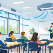
A classroom can feel cool and still have inadequate outdoor air. That distinction matters when students, teachers, and staff spend full days in densely occupied spaces. A school ventilation retrofit is not simply a matter of replacing rooftop equipment. It is an engineering decision that affects indoor air quality, moisture control, energy use, permitting, construction sequencing, and the school’s ability to operate without disruption.

For Florida school facilities, the challenge is amplified by heat, humidity, aging HVAC infrastructure, and schedules that leave little room for extended shutdowns. The right retrofit begins with measured conditions and a clear compliance strategy, then moves into a design that can be built, inspected, and maintained.

Start With the Building, Not the Equipment

Many ventilation projects begin with a request for larger air-conditioning units or new air-cleaning devices. Those solutions may be appropriate, but they should follow an assessment, not replace one. Oversizing equipment can create short cycling, poor humidity removal, higher first cost, and uneven classroom comfort. Adding outdoor air without confirming cooling and dehumidification capacity can introduce moisture problems rather than solve them.

A practical assessment reviews how the existing system actually performs. That includes HVAC equipment age and condition, available outside-air pathways, filter racks, duct leakage, exhaust systems, controls, occupancy patterns, and complaint history. Classrooms, cafeterias, gyms, auditoriums, restrooms, nurse’s offices, and specialty labs each have different ventilation and pressure requirements. A system that serves a typical classroom well may be unsuitable for a science lab or a high-occupancy multipurpose room.

The engineering team should also verify electrical capacity. New dedicated outdoor-air equipment, energy recovery systems, larger fans, or upgraded controls can change panel loads, feeder requirements, and emergency-power considerations. Addressing these constraints early prevents a mechanical upgrade from becoming an unplanned electrical redesign during construction.

What a School Ventilation Retrofit Should Solve

The strongest projects define performance goals before selecting equipment. In most cases, the objective is a balanced combination of outdoor-air delivery, filtration, humidity control, pressure relationships, and dependable controls.

Outdoor air must reach occupied areas at the intended rate, not merely enter the building somewhere upstream. Damaged dampers, disconnected ducts, clogged intake screens, failed actuators, and poorly balanced distribution systems can all prevent that result. Testing, adjusting, and balancing are therefore essential parts of the work, not a final administrative step.

Filtration needs the same discipline. A higher-efficiency filter can improve particle capture, but it also increases pressure drop. If the existing fan cannot overcome that added resistance, airflow may decline. The design must confirm fan capability, filter housing integrity, access for maintenance, and the operating cost of replacement filters. Portable air cleaners can provide targeted support in selected rooms, but they do not correct deficient outside-air ventilation, failing exhaust, or building pressure problems.

Humidity control deserves particular attention in South Florida. High indoor humidity can create comfort complaints, condensation, mold risk, and material deterioration even when the thermostat reads an acceptable temperature. Ventilation changes must be coordinated with sensible and latent cooling loads so the system can manage the moisture introduced with outdoor air.

Design for Code Compliance and Real Operations

A school ventilation retrofit must satisfy applicable Florida Building Code requirements, local jurisdiction amendments, mechanical code provisions, electrical requirements, fire and smoke protection requirements, and the project’s specific occupancy conditions. Depending on the facility and scope, applicable standards for ventilation design, energy performance, and indoor environmental quality may also inform the engineering approach.

Code compliance is not limited to airflow calculations. New penetrations can affect roof warranties and structural framing. Ductwork crossing fire-rated assemblies may require properly detailed fire and smoke dampers. Equipment locations must preserve service access, rooftop clearances, drainage, and safe maintenance paths. Controls must be installed and commissioned in a way that facilities staff can understand and operate.

Permitting documentation should show the full coordination between mechanical, electrical, structural, architectural, and fire protection disciplines. Clear plans, schedules, control diagrams, equipment data, and calculations reduce review comments and prevent contractors from making field assumptions that compromise the design intent.

Common retrofit approaches

The appropriate solution depends on the condition of the existing system, the building layout, the budget, and whether work can occur during occupied periods. Common approaches include:

  • Repairing and recommissioning existing outside-air dampers, exhaust fans, controls, and distribution systems when core equipment remains serviceable.
  • Adding dedicated outdoor-air systems to provide measured, conditioned ventilation independently from classroom cooling equipment.
  • Upgrading air-handling units, fan coils, rooftop units, or split systems where age, capacity, reliability, or moisture control has become a limiting factor.
  • Improving filtration, duct sealing, return-air pathways, and building automation controls to maintain airflow and identify operating faults.
  • Installing energy recovery equipment where the outdoor-air load and operating schedule support the added capital cost and maintenance responsibility.

There is no universal answer. A targeted controls and balancing project can produce meaningful results in one campus, while another requires full equipment replacement because the existing system cannot reliably deliver design airflow or manage humidity.

Protect School Operations During Construction

A technically sound design can still fail operationally if construction planning is weak. Schools need a phased approach that protects occupants, preserves instruction, and avoids exposing finished areas to dust, noise, or unplanned shutdowns.

For occupied facilities, contractors should establish work zones, infection-control and dust-control measures where applicable, delivery routes, material staging areas, and procedures for isolating equipment. Shutdown windows should be planned around testing, meals, after-school programs, examinations, and special events. Roof work needs careful coordination during hurricane season and wet-weather periods, particularly when equipment curbs, flashing, or electrical penetrations are involved.

Temporary cooling and ventilation may be necessary when replacing equipment that serves occupied wings. This cost should be evaluated early rather than treated as a contractor contingency. A project that saves money on equipment but forces repeated classroom relocations can create substantial operational costs for the school.

Commissioning should occur before final acceptance, with school representatives included in the process. Verify outdoor-air operation, airflow balance, temperature and humidity control, exhaust performance, alarms, scheduling, and trend data. Facilities staff should receive clear closeout documentation, control sequences, equipment manuals, filter specifications, and a maintenance plan suited to the installed system.

Build a Budget Around Lifecycle Value

First cost matters, particularly for public, charter, private, and campus facilities managing limited capital budgets. Yet the lowest bid may not represent the lowest long-term cost. Frequent equipment failures, inaccessible filters, excessive fan energy, unresolved moisture, or difficult controls can consume the savings quickly.

A useful budget distinguishes between immediate corrective work and longer-term capital improvements. It should also account for permitting, design, electrical upgrades, structural supports, roof restoration, controls integration, testing and balancing, commissioning, temporary conditioning, and contingency conditions discovered in concealed spaces.

For multi-building campuses, phasing can be a responsible path forward. Prioritize areas with documented ventilation deficiencies, chronic humidity complaints, repeated equipment failures, high occupancy, or vulnerable populations. A campus-wide assessment creates a defensible sequence for capital planning and helps owners avoid reactive replacements that do not support a cohesive system strategy.

Engineering Decisions That Stand Up to Review

A ventilation retrofit should leave the school with more than new equipment. It should provide documented design criteria, code-aware calculations, permit-ready construction documents, and verified performance at turnover. That documentation supports maintenance decisions, future renovations, capital planning, and accountability to boards, administrators, insurers, and regulators.

Licensed PE oversight brings value where ventilation changes affect building systems, life safety, electrical infrastructure, roof conditions, or permit compliance. For South Florida facilities, an integrated review is especially valuable because cooling, humidity, electrical service, and weather exposure are closely connected.

The best time to resolve a ventilation risk is before a classroom is disrupted, a permit review is delayed, or a moisture issue spreads beyond a single room. Start with a measured assessment, establish the required performance, and move forward with a design that protects students, staff, schedules, and the long-term value of the facility.

Solar Capacity Impacts on Florida Buildings

A proposed rooftop solar system can look straightforward on a site plan, then expose costly constraints once it reaches electrical review. Solar capacity impacts are not limited to how many kilowatts a roof can produce. They affect service equipment, feeder loading, utility interconnection, structural support, fire access, permitting scope, construction sequencing, and the building owner’s long-term liability.

For commercial properties, multifamily communities, and condominium associations, the right question is not simply, “How much solar can fit?” It is, “What system can this building safely support, permit, operate, and maintain?” A disciplined engineering review answers that question before equipment is purchased or schedules are committed.

Why solar capacity impacts extend beyond the roof

Solar capacity is commonly described in direct-current kilowatts, based on the output rating of the photovoltaic modules. That rating matters, but it is only one part of the design. The inverter converts DC power to AC power, and that AC output is what connects to the building electrical system and the utility grid.

A building may have adequate roof area for a large array while lacking practical capacity at the electrical point of connection. Existing switchgear may be fully utilized, deteriorated, obsolete, or unavailable for modification. A main distribution panel may have limited bus rating, no suitable breaker space, or a configuration that makes a new backfed source impractical without upgrades.

This is why a panel count is not an electrical capacity analysis. A project must account for the service rating, main breaker rating, busbar rating, feeder ampacity, available fault current, protective-device coordination, and the specific interconnection method. The National Electrical Code governs much of this work, but a code-compliant path still has to fit the real conditions of the building and the requirements of the serving utility.

The practical difference between production and capacity

Production is the energy a solar array is expected to generate over time, usually measured in kilowatt-hours. Capacity is the instantaneous electrical output or load-handling capability, commonly measured in kilowatts or amperes. Owners need both figures, but they solve different problems.

A system with strong annual energy production may still require a service upgrade because of its AC interconnection characteristics. Conversely, a building with ample electrical capacity may face limits from roof structure, fire setbacks, utility rules, or project economics. Treating these constraints as one issue leads to avoidable change orders.

Electrical capacity must be verified before design advances

The most valuable solar decision often happens before final equipment selection. An existing-condition electrical survey should document the service entrance, switchgear, panelboards, transformer capacity, feeders, grounding and bonding conditions, available spaces, labels, equipment condition, and accessible pathways.

Load calculations then establish how the building uses its electrical service. This is especially relevant for properties planning other electrical improvements. EV charging stations, central HVAC replacements, electric water heating, battery storage, tenant build-outs, and kitchen upgrades can all compete for capacity. A solar project should be evaluated within the broader electrical plan, not as an isolated improvement.

For a multifamily property, for example, a common-area solar system may offset house loads while the community also considers EV charging. The solar installation does not automatically create capacity for chargers. In many cases, EV charging increases demand at times when solar output is reduced or unavailable. The property may need load management, service upgrades, or phased infrastructure planning to achieve both goals responsibly.

Interconnection rules shape the feasible system size

The point where solar connects to the electrical system is a core design decision. Depending on the existing equipment and utility requirements, the system may connect on the load side of the service, through a supply-side connection, at a dedicated distribution point, or through new service equipment.

Each option carries different requirements for conductor sizing, overcurrent protection, disconnecting means, labeling, access, and utility approval. The selected method can materially change the maximum system size that is practical without major electrical reconstruction.

Utility review is also not a final administrative step. It can influence transformer needs, meter arrangements, protection settings, export limitations, and construction timing. Early coordination helps prevent a situation where permits are nearly complete but the proposed system cannot be interconnected as designed.

Roof structure and fire access can set hard limits

Electrical capacity is only one side of solar feasibility. Rooftop arrays introduce dead load, wind uplift forces, attachment loads, and localized stresses that the roof framing and deck must safely resist. Florida conditions demand particular attention to wind design, waterproofing details, corrosion exposure, and the existing roof’s condition.

A structural review should confirm whether the roof can support the proposed array and mounting system without compromising the building envelope or creating a costly remediation scope. On an aging building, the remaining service life of the roof matters as much as its calculated strength. Installing panels over a roof due for replacement can turn a future reroof into a significant removal and reinstallation expense.

Fire protection and emergency access must also be addressed. Array layout needs to preserve required pathways, setbacks, equipment clearances, and roof access as applicable to the building and authority having jurisdiction. Inverters, disconnects, rapid-shutdown equipment, and signage must be coordinated so first responders and maintenance personnel can identify and isolate the system safely.

These requirements are not design details to resolve after procurement. They can reduce usable roof area and alter system capacity. A concept that maximizes module count on paper may be unpermittable once access and life-safety requirements are applied.

Solar capacity impacts project cost in predictable ways

The lowest equipment price is not always the lowest project cost. A larger array may generate more energy, yet trigger expensive upgrades to switchgear, transformers, feeders, or roof structure. A slightly smaller system may provide stronger overall value if it connects cleanly to existing infrastructure and avoids disruptive construction.

Owners should evaluate at least three cost categories: the solar installation itself, enabling infrastructure, and lifecycle obligations. Enabling work can include electrical upgrades, structural reinforcement, reroofing, utility modifications, engineering, permits, and inspections. Lifecycle obligations include monitoring, maintenance access, roof repairs, insurance considerations, and eventual equipment replacement.

For associations and commercial owners, phased planning can be the prudent answer. A property may prepare conduits, electrical rooms, roof zones, and service capacity now while installing only the first phase of solar. This approach can protect the long-term plan without forcing a capital expense before the property is ready.

A permit-ready process reduces late-stage surprises

A reliable solar project begins with field verification, not assumptions from old drawings. Record drawings can be useful, but equipment may have been replaced, altered, or modified over decades of operation. A licensed professional engineer can evaluate the conditions that actually exist and produce documentation aligned with the intended scope.

A permit-ready package typically coordinates structural details, electrical one-line diagrams, equipment ratings, conductor and overcurrent protection sizing, grounding and bonding, rapid shutdown, roof attachment details, site-specific wind considerations, and required notes and calculations. The level of documentation should match the building, jurisdiction, utility, and project complexity.

This coordination matters during construction as well. Contractors need clear installation requirements, and owners need confidence that material substitutions or field changes do not undermine the approved design. Inspection support and responsive engineering review help keep a valid field issue from becoming a schedule delay or code violation.

Questions owners should resolve early

Before authorizing a solar proposal, property decision-makers should obtain clear answers to a few practical questions. What is the building’s verified electrical capacity at the intended connection point? What upgrades are required, and who is responsible for each cost? Can the roof support the system for its expected service life? How will fire access, roof drainage, waterproofing, and maintenance be preserved? What does the utility require before interconnection can occur?

It is also wise to ask how the project fits future loads. A solar installation designed without considering planned EV charging, electrification, tenant expansion, or major mechanical replacement can constrain the next capital project. The best design protects flexibility rather than consuming it.

For Florida property owners, solar can be a sound investment when it is treated as a building-system project rather than a rooftop purchase. Early electrical and structural engineering creates a clearer path through permitting, construction, and operation – and gives owners a basis for making capacity decisions with confidence before costs become commitments.

Florida Resilience Starts With Building Decisions

A roof leak after a wind event, a failed electrical component during peak cooling demand, or a deferred concrete repair can quickly become more than a maintenance issue. For a property owner or condominium board, it can disrupt operations, expose occupants to risk, complicate insurance discussions, and create unplanned capital costs. Florida resilience is built through earlier, better building decisions: understanding existing conditions, correcting deficiencies before they spread, and designing improvements that perform under real operating conditions.

For commercial and multifamily properties, resilience is not a single upgrade or a hurricane-season checklist. It is a disciplined approach to structural, electrical, mechanical, plumbing, and fire protection systems throughout a building’s life cycle. The objective is practical: keep the property safe, code-compliant, insurable, functional, and positioned to retain value.

Florida Resilience Is a Building Performance Issue

Florida buildings operate under persistent stress. Heat, humidity, wind-driven rain, salt exposure in coastal areas, heavy cooling loads, aging infrastructure, and severe weather all affect how building systems perform. A property can appear well maintained while concealed corrosion, water intrusion, undersized electrical capacity, or deteriorated fire protection components continue to develop behind finishes and above ceilings.

That is why resilience cannot be measured only by whether a building remains standing after a major storm. A resilient property is one that can be assessed quickly, operated safely, repaired efficiently, and returned to normal use with clear documentation. It has systems designed and maintained with realistic loads, known vulnerabilities, access for inspection, and a defined path for corrective work.

For owners, this approach also reduces uncertainty. When engineering records, inspection findings, repair scopes, and permit documents are organized, decision-makers can prioritize capital spending based on actual risk rather than urgency alone. That distinction matters when budgets are limited and multiple building needs compete for funding.

Start With Existing Conditions, Not Assumptions

The most effective resilience planning starts with a credible understanding of the property as it exists today. Original plans may not reflect renovations, equipment replacements, tenant improvements, undocumented repairs, or changes in code requirements. A visual walkthrough can identify obvious concerns, but many decisions require licensed engineering evaluation and targeted investigation.

Structural reviews may evaluate concrete distress, cracking patterns, corrosion-related deterioration, water intrusion pathways, balconies, roofs, exterior elements, or other conditions that affect safety and durability. Electrical evaluations may examine service capacity, panel condition, grounding and bonding, emergency systems, load calculations, and the impact of planned additions such as EV charging stations. MEP reviews can identify drainage issues, aging equipment, ventilation limitations, piping deterioration, or equipment supports that require attention.

The scope should match the property and the decision at hand. A small repair does not always require a full building assessment. Conversely, a limited visual review should not be treated as proof that a complex, aging building has no concealed risks. The right level of investigation depends on the observed conditions, building age, occupancy, proposed work, and applicable regulatory requirements.

Inspection Findings Need a Path to Action

An inspection report has value only when it leads to informed action. Property stakeholders need findings stated clearly, with the observed condition, likely consequence, recommended next step, and relative priority understood by the people responsible for budgets and operations.

In many cases, the best outcome is not immediate replacement. A properly designed repair, protective coating system, drainage correction, equipment support modification, or electrical upgrade can extend useful life while addressing the condition that caused the problem. In other cases, deferred replacement creates a larger liability than prompt action. Engineering judgment helps distinguish between these scenarios.

Design for the Conditions Florida Actually Delivers

Resilient design is specific. It considers local exposure, building use, existing construction, maintenance capability, and the systems already in place. A solution that works for an inland office building may not be appropriate for a coastal multifamily property with elevated humidity, salt-laden air, and year-round occupancy.

Water management is a common example. Water intrusion can affect structural elements, electrical systems, finishes, indoor air quality, and tenant satisfaction. A durable solution may require more than patching a visible leak. It may involve identifying failed sealant transitions, deteriorated waterproofing, inadequate drainage slopes, roof detailing, wall penetrations, or HVAC condensate issues. Correcting the source protects the repair investment.

Electrical resilience requires similar discipline. Florida properties increasingly face higher electrical demand from modern HVAC equipment, commercial operations, tenant loads, standby power needs, and EV charging. Adding equipment without a capacity analysis can overload existing infrastructure or trigger expensive changes late in the project. Load calculations, equipment evaluations, feeder analysis, and code-compliant design help owners understand what their systems can support before construction begins.

Fire protection systems also require a performance-based mindset. A building’s protection depends on more than installed components. System modifications, occupancy changes, tenant build-outs, renovations, and impairments can affect compliance and life-safety performance. Clear, coordinated fire protection design helps prevent permit delays and avoids field conflicts that can disrupt construction schedules.

Compliance Supports Resilience, But It Is Not the Entire Goal

Florida Building Code, NEC, NFPA standards, local permitting requirements, and mandatory inspection obligations establish essential baselines. Meeting them is necessary, but a minimum code path does not automatically resolve every long-term operating risk.

For example, a code-compliant replacement may still be difficult to maintain, poorly coordinated with adjacent systems, or inadequate for expected future demand. An owner planning a phased renovation, electrification project, or EV charging installation may benefit from designing backbone capacity now, even if every future component is not installed immediately. The added upfront cost must be evaluated against expected growth, construction disruption, available budget, and the cost of reopening finished areas later.

This is where project-specific engineering matters. The correct answer is rarely to overbuild every system. It is to document the current condition, identify foreseeable requirements, and make deliberate decisions about what should be completed now, what should be prepared for, and what can be monitored safely.

Permit-Ready Documents Protect Schedule and Scope

Resilience work often begins under pressure, especially after an inspection finding, code violation, storm-related damage, or equipment failure. Rushed work without complete documentation can create a different set of problems: unclear contractor pricing, incomplete repairs, permit comments, change orders, and delays in closing out the work.

Construction-ready drawings and specifications create a clear basis for bidding, permitting, and field execution. They define repair extents, materials, connections, system requirements, and relevant code considerations. They also give the owner a record of what was intended, which is valuable during inspections, warranty discussions, future renovations, and property transactions.

For larger or more complex work, coordination among structural, electrical, mechanical, plumbing, and fire protection disciplines is especially important. A new electrical room, generator connection, pump modification, or rooftop equipment replacement can affect several systems at once. Addressing those interfaces before construction protects both schedule and budget.

Build a Capital Plan Around Risk and Consequence

No property can complete every recommended improvement at once. A practical resilience plan ranks work by life safety, regulatory exposure, likelihood of failure, consequence of failure, cost escalation risk, and operational impact.

A life-safety concern, active water intrusion affecting electrical equipment, or condition tied to a mandatory inspection finding generally requires faster action than a cosmetic issue. Yet lower-priority items should not disappear from view. Small deficiencies can become expensive when they are repeatedly deferred or when they are allowed to affect adjacent systems.

Boards, facility managers, and owners benefit from a multi-year plan that separates immediate corrective work from near-term renewals and longer-range improvements. This allows reserves, financing, tenant communications, procurement, and construction sequencing to be planned with greater confidence. It also creates a better record of responsible property stewardship.

Resilience Depends on Accountability During Construction

Even strong design documents need disciplined execution. Field conditions may differ from assumptions, concealed damage may be discovered, and substitutions may be proposed due to availability or cost. Those moments require timely review, clear communication, and decisions grounded in code compliance and building performance.

Milestone inspections, progress observations where appropriate, and responsive engineering support help keep corrective work aligned with the approved intent. They can also identify issues before finishes conceal them or before a minor deviation becomes a costly rework item. For owners, this oversight is not an administrative extra. It is part of protecting the value of the construction investment.

Boukzam PE Consulting supports this process with licensed PE oversight, practical design documentation, inspections, and corrective engineering focused on real construction conditions. The goal is clear, code-compliant work that moves from identified concern to defensible resolution.

A resilient Florida property is not defined by a single inspection, repair, or upgrade. It is built through consistent decisions that respect the building’s condition, its occupants, its operating demands, and the consequences of waiting. When the next concern appears, clear engineering direction gives owners a stronger place to start.

Accessibility Retrofit Guide for Florida Properties

A ramp that ends at a heavy, noncompliant door is not accessibility. Neither is an accessible restroom reached only by a route with an abrupt level change. For owners and managers, an accessibility retrofit guide must address the complete path of travel, the building systems that support it, and the permit decisions that can affect cost and schedule.

For commercial and multifamily properties, accessibility work is often prompted by a renovation, a tenant improvement, a resident complaint, a code review, an inspection finding, or a broader capital plan. The best projects do not treat the issue as a last-minute architectural adjustment. They establish existing conditions early, define the applicable requirements, and produce coordinated documents that can be permitted and built without avoidable rework.

Start With the Retrofit Trigger, Not the Product

An accessibility retrofit does not begin by selecting grab bars, ramps, or door operators. It begins by identifying why the work is being performed and which rules apply. In Florida, projects may involve the Florida Building Code Accessibility provisions, the Florida Existing Building Code, federal Americans with Disabilities Act requirements, fair housing obligations for covered multifamily housing, local permitting requirements, and contractual or insurer requirements.

The applicable standard depends on the property type, occupancy, scope of work, date of construction, and whether the area serves the public, residents, employees, or guests. A hotel lobby, retail suite, condominium clubhouse, medical office, and apartment leasing office can each present different obligations. A renovation can also trigger path-of-travel upgrades beyond the room receiving the new finishes.

This is where property teams can lose control of a project. A contractor may price a visible correction while an authority having jurisdiction identifies related work during plan review or inspection. A focused existing-conditions assessment helps establish the full scope before construction pricing is locked in.

Accessibility Retrofit Guide: Assess the Entire Route

A practical assessment follows a person’s actual trip through the property. Start at the site arrival point and continue through parking, passenger drop-off areas, sidewalks, entrances, interior circulation, service counters, restrooms, amenities, and egress-related features. Measurements matter, but so do slopes, transitions, maneuvering clearances, hardware operation, obstructions, and the way doors and gates function in daily use.

Site Access and Parking

Accessible parking is more than a striped stall. The number, size, signage, location, access aisle, vertical clearance, surface condition, and connection to an accessible route all require review. In South Florida, settlement, drainage modifications, resurfacing, and repeated storm exposure can create cross slopes or abrupt changes that make a once-compliant route difficult to use.

The accessible route from parking to the entrance deserves the same scrutiny as the parking space itself. Look for curb ramps that direct users into traffic, deteriorated pavement, loose pavers, drainage grates, tree-root displacement, and gates that require excessive force. Correcting these conditions early can reduce trip hazards while improving accessibility and site appearance.

Entrances, Doors, and Vertical Access

At building entrances, review clear width, thresholds, maneuvering space, hardware, closing force, signage, and whether an accessible entrance is available during normal operating hours. A secondary entrance labeled as accessible may not satisfy the practical needs of tenants or visitors if it is locked, poorly signed, or requires staff assistance.

Multi-story buildings require a clear strategy for vertical access. Elevators, platform lifts, and ramps serve different conditions and budgets. A ramp can be a durable solution where elevation changes and available space allow, but its required length, landings, handrails, edge protection, drainage, and impact on circulation can make it impractical. A lift may fit a constrained footprint, yet it adds equipment maintenance, power, weather protection, and operational reliability considerations. Engineering review should compare the life-cycle impact, not just initial installation cost.

Interior Common Areas and Amenities

Interior retrofits commonly involve restrooms, corridors, reception areas, drinking fountains, kitchens, locker rooms, pools, fitness rooms, and meeting spaces. Small conflicts can have major consequences. A restroom may contain the correct fixtures but lack required clear floor space because a partition, dispenser, or trash receptacle occupies the turning area.

For condominiums and apartments, common-area amenities are frequent risk points. Clubhouses, pool decks, mailrooms, leasing offices, laundry rooms, and package areas should be reviewed as part of the same access plan. Individual dwelling units require a separate analysis from common spaces, particularly when fair housing design and construction requirements apply.

Coordinate Architecture With MEP and Life Safety Systems

Accessibility construction affects more than walls and finishes. Door operators need electrical power and controls. A relocated restroom can affect plumbing connections, venting, hot-water distribution, electrical circuits, lighting controls, and fire-rated assemblies. Modified corridors and lobbies can affect exit access, fire alarm devices, sprinkler coverage, and emergency communication features.

This is why isolated field fixes often become expensive. A new accessible counter may block a required egress path. A door alteration may change fire-rating or hardware requirements. A ramp built around an existing electrical room may limit required equipment working clearance. Coordinated design documents identify these conflicts before they become a change order.

For older properties, verify available electrical capacity before committing to automatic doors, lifts, elevator upgrades, or revised mechanical equipment. The cost of a new feeder, panel modification, or emergency-power requirement can materially change the project budget. These are not reasons to delay accessibility improvements. They are reasons to develop a complete scope with clear engineering decisions.

Build a Phased Plan That Preserves Operations

Many accessibility corrections can be delivered in phases, especially in occupied communities, hotels, retail centers, offices, and healthcare-adjacent facilities. The first phase should address conditions that create the greatest safety exposure, prevent use of key public areas, or are tied to an active permit or enforcement matter. Later phases can align with scheduled renovations, pavement replacement, restroom refreshes, or amenity upgrades.

A phased approach works only when the long-term plan is documented. Rebuilding a sidewalk today without accounting for a future curb ramp or entrance reconstruction can result in duplicated demolition. Likewise, replacing doors without confirming final hardware, clearance, and power needs may waste a recently completed improvement.

Construction sequencing is equally important. Maintain accessible routes whenever feasible, provide clear temporary signage, and coordinate work hours around residents, customers, and staff. Temporary access measures should be reviewed for safety and usability rather than treated as an afterthought.

Document Decisions for Permitting and Liability Control

Good accessibility work produces a record that supports permitting, construction, inspections, and future property management. Existing-condition photos, field measurements, code analysis, drawings, specifications, calculations where needed, product data, and inspection records provide a defensible basis for the work performed.

Avoid relying solely on manufacturer claims or generic details. A compliant product can be installed in a noncompliant location. Conversely, a field condition may require a customized solution that must be detailed for structural support, waterproofing, drainage, electrical service, or fire protection coordination.

Licensed professional engineering oversight adds value when modifications affect structural elements, building systems, life safety components, or complex existing conditions. It also helps owners distinguish between a low-cost correction that will pass inspection and a low-cost correction that simply moves the problem to another location.

Choose Corrections That Will Perform Over Time

The least expensive installation is not always the lowest-cost ownership decision. Exterior railings must withstand corrosion and repeated use. Detectable warnings, walking surfaces, and striping must remain visible and stable. Door operators must be maintained. Accessible hardware must continue to function after years of daily operation.

For Florida properties, specify materials and details that account for moisture, salt exposure where applicable, intense sun, drainage, and heavy occupancy. The right solution should be code-aware, maintainable, and suited to the building’s operations. It should also be clear enough for facility staff to inspect and maintain after the contractor leaves.

A disciplined accessibility retrofit protects more than code compliance. It gives residents, visitors, employees, and customers a usable building while helping owners control liability, avoid schedule disruption, and preserve long-term property value. The right first step is a measured assessment that turns scattered conditions into a clear, buildable plan.

EV Charging Demand Trends for Florida Properties

A parking area can look fully capable of supporting EV charging until the electrical calculations begin. For many Florida properties, the limiting factor is not the number of parking spaces or the desire to offer charging. It is available service capacity, distribution equipment, feeder pathways, utility coordination, and a design that can be permitted and expanded without expensive rework. EV charging demand trends are making that early engineering review a capital-planning priority.

For condominium boards, multifamily owners, developers, and facility managers, the question is no longer whether electric vehicles will affect parking infrastructure. The operational question is how quickly demand will arrive at a specific property and what level of investment is justified now. A practical answer requires more than installing a few chargers. It requires a code-compliant plan built around actual electrical capacity, resident or customer behavior, parking turnover, and future expansion.

EV Charging Demand Trends Are Changing Project Planning

Demand is growing unevenly across property types. A luxury condominium with assigned parking may face a small but persistent group of owners requesting overnight charging. A hotel, retail center, or medical office may need visible charging amenities for guests but experience short, variable dwell times. Industrial facilities may be planning fleet electrification, where charging becomes a critical operating load rather than a tenant convenience.

That difference matters. Installing the same equipment at every site can create either a costly underused asset or a system that cannot meet real demand. Property decision-makers should begin with the use case: Who will charge, how long will vehicles remain parked, how often will charging occur, and who is responsible for electricity costs?

Florida’s market adds another layer of urgency. Dense multifamily development, destination travel, seasonal occupancy, and an expanding base of electric vehicles can increase demand in locations where electrical rooms and site infrastructure were never designed for charging loads. In older properties, available capacity may already be constrained by air-conditioning, common-area equipment, elevators, pumps, and planned renovations.

Electrical Capacity Is the First Design Decision

The number printed on a charging station does not tell the full story. A Level 2 charger may be rated for a substantial continuous load, and several units operating at once can quickly affect existing switchgear, transformers, panels, feeders, and service capacity. The National Electrical Code treats EV charging equipment as a continuous load, which directly affects conductor, overcurrent protection, and equipment sizing.

A qualified engineering assessment should review the existing one-line diagram, utility service information, panel schedules, field conditions, and available capacity. Where documentation is outdated or incomplete, field verification becomes especially important. Assumptions made from an old panel schedule can lead to permit delays, change orders, or equipment that cannot be safely connected.

Capacity analysis does not always result in a service upgrade. In some cases, load calculations show that the building can support a limited initial installation. In others, managed charging can keep aggregate demand within a defined limit. For properties with little remaining capacity, a service, transformer, or distribution upgrade may be unavoidable. The right path depends on the actual system, not a generic charger count.

Why Load Management Has Become More Valuable

Smart load management allows multiple chargers to share a defined electrical capacity. When few vehicles are connected, more power can be available to each vehicle. As demand rises, the system can reduce output across chargers to avoid exceeding the site limit.

This approach can reduce near-term upgrade costs and support phased deployment, particularly in multifamily garages and employee parking areas. It is not a substitute for proper engineering. The design still must account for the charging equipment, controls, communications requirements, electrical protection, and the building’s peak-demand profile.

There are trade-offs. A managed system may extend charging time during high-demand periods, which may be acceptable for overnight resident charging but less suitable for a commercial site where customers expect a quick turnaround. Owners should establish realistic service expectations before selecting charging equipment or a network provider.

Designing for Expansion Costs Less Than Retrofitting Later

The strongest EV charging projects separate immediate installation from long-term readiness. A property may install four active chargers today while preparing conduit routes, spare panel capacity, equipment space, and pathways for additional chargers in later phases. That preparation can prevent future trenching, demolition, garage disruption, and repeated permit work.

For new construction, EV readiness should be coordinated early with electrical rooms, parking layouts, structural conditions, fire protection systems, architectural finishes, and utility requirements. Waiting until construction documents are complete can force rushed revisions and reduce available routing options.

For existing buildings, phased work is often more practical. The first phase can establish a dedicated charging distribution system, metering strategy, and scalable communications architecture. Later phases can add charging stations as demand justifies the investment. This approach helps owners control capital expenses while avoiding a patchwork of independently installed equipment.

A future-ready plan commonly addresses four areas:

  • Dedicated electrical capacity or a documented strategy for managed capacity
  • Conduit, sleeves, and accessible pathways to parking locations
  • Physical space for future panels, transformers, or switchgear where needed
  • A clear approach to metering, billing, network access, and operational responsibility

These details should be coordinated with the property’s operating model. In a condominium, the association may need a consistent policy for resident requests, installation standards, electricity reimbursement, maintenance, and liability. In a retail or hospitality setting, ownership may prioritize public access, payment systems, visibility, and uptime. The equipment is only one part of the program.

Code Compliance Extends Beyond the Charger

EV charging design must be coordinated with applicable electrical, building, fire, accessibility, utility, and local permitting requirements. The relevant requirements can vary based on the site, jurisdiction, occupancy, equipment type, parking layout, and whether the project involves new construction or an existing facility.

NEC requirements affect load calculations, wiring methods, grounding and bonding, overcurrent protection, disconnecting means, and the installation of electric vehicle power transfer systems. Florida Building Code provisions and local requirements can affect parking accessibility, site work, structural mounting, fire-rated assemblies, equipment clearances, and permitting documentation. NFPA considerations may also apply to the broader electrical and life-safety environment.

Accessibility deserves early attention. An accessible charging space is not simply a standard accessible parking space with a charger added beside it. The parking layout, access aisle, route to building entrances, charging-cable management, bollards, and equipment placement must work together. Poor layout decisions can create barriers for users, expose equipment to vehicle impact, or require costly correction after inspection.

In parking garages, ventilation, fire protection coordination, vehicle circulation, and protection of electrical equipment also deserve review. In coastal and high-humidity environments, equipment location, corrosion resistance, and weather exposure can influence long-term performance and maintenance costs.

The Utility Timeline Can Shape the Entire Schedule

When an EV project requires a larger service, transformer work, or utility-side modifications, utility coordination can become a critical schedule item. Lead times may affect construction sequencing, equipment procurement, and opening dates. This is one reason electrical capacity should be evaluated before a property commits to charger quantities or announces an installation date.

Clear permit-ready documents reduce uncertainty. They should identify the charging equipment, connected load, distribution modifications, feeder routing, protective devices, site layout, mounting details, and applicable notes needed for construction and inspection. A licensed professional engineer can provide the calculations and coordinated documentation necessary to move a complex project forward with confidence.

Make Demand Data Part of Property Planning

The best time to assess EV charging is before demand becomes an urgent resident complaint, lease negotiation issue, or redevelopment constraint. Owners can begin with a practical inventory: available electrical capacity, parking conditions, existing drawings, planned capital improvements, likely user groups, and whether billing or access control will be required.

From there, an engineered feasibility review can distinguish between a modest first phase, a managed charging program, and a larger infrastructure upgrade. That clarity protects budgets, improves permit readiness, and helps avoid installing equipment that does not match the property’s actual needs.

EV charging is becoming part of a building’s long-term electrical strategy. A disciplined plan gives property stakeholders a better way to respond to demand: build what is needed now, preserve a path for what comes next, and keep safety, compliance, and operational performance in view at every phase.

When Are Smoke Controls Required in Buildings?

A smoke-control decision can change a project’s mechanical scope, electrical backup requirements, sequence of operations, and permit timeline. So, when are smoke controls required? In Florida, the answer begins with the Florida Building Code and the adopted local requirements, then depends on the building’s use, height, geometry, fire strategy, and the specific condition being evaluated.

Smoke control is not a standard exhaust fan added late in construction. It is an engineered life-safety system intended to manage smoke movement during a fire so occupants can evacuate, responders can operate, and protected paths remain usable for the required period. Getting that distinction right early protects both the project budget and the building’s long-term compliance position.

When Are Smoke Controls Required Under Code?

The Florida Building Code, Building includes smoke-control provisions that generally align with the model-code framework in Section 909. A smoke-control system is required where another code provision specifically calls for it. The requirement is therefore tied to the building condition, not simply to owner preference or square footage.

Common triggers include atriums, covered mall buildings, certain high-rise conditions, underground buildings, smokeproof enclosures, and some institutional or special-use occupancies. A project may also require smoke control because of an alternative fire-protection approach, a performance-based design, or a condition imposed during plan review.

The exact trigger must be confirmed against the edition of the Florida Building Code adopted for the project, applicable local amendments, and the complete building design. A single change in occupancy classification, number of stories, atrium configuration, or egress arrangement can alter the analysis.

Atriums and interconnected floor openings

Atriums are among the most familiar smoke-control applications. When multiple stories are connected through an open volume, smoke can migrate rapidly beyond the floor of origin. The fire and smoke strategy may require mechanical exhaust, make-up air, barriers, shutters, or a combination of measures to keep smoke from compromising exits and adjacent levels.

Not every visually open space is treated the same way. Code exceptions and design options may apply based on the opening size, separation method, sprinkler protection, and the building’s overall arrangement. That is why an early code review is less expensive than assuming an atrium system is required or, just as costly, overlooking one until permit review.

High-rise buildings and smokeproof enclosures

High-rise buildings present longer evacuation paths, more complex firefighter operations, and greater reliance on protected stairs and fire-service systems. Smoke-control requirements can apply to specific spaces or systems within the building, including smokeproof enclosure designs.

A smokeproof enclosure is not merely an enclosed stair. Depending on the selected code-compliant method, it may rely on natural ventilation, mechanical ventilation, or pressurization to limit smoke entry. The selected approach has direct implications for fan sizing, power supply, controls, duct routing, door forces, testing, and coordination with the fire alarm system.

For condominium boards, owners, and managers of existing high-rise properties, renovations deserve particular attention. A lobby reconfiguration, stair enclosure modification, generator upgrade, or HVAC replacement can affect an existing smoke-management sequence and expose gaps in older documentation.

Underground and special-use buildings

Below-grade buildings can require smoke control because smoke has fewer natural paths to disperse and occupants may have limited egress options. Special-use conditions can also create requirements that are not apparent from the building’s exterior. Examples may include certain detention-related occupancies, large assembly environments, covered mall configurations, and facilities using engineered fire-safety strategies.

The point is not that every parking garage, lower-level tenant space, or large lobby needs a smoke-control system. The point is that these conditions require disciplined evaluation. Smoke control must be based on the code trigger and the fire scenario it is intended to address.

What a Smoke-Control System Actually Includes

A compliant system is a coordinated package, not a single piece of equipment. Depending on the design, it can include smoke-exhaust fans, supply or make-up air fans, stair or zone pressurization equipment, smoke dampers, rated shafts, ductwork, control panels, detectors, manual firefighter controls, and standby power.

It also requires a clear sequence of operations. When a fire alarm condition occurs, the system must know which fans start, which dampers move, which air-handling units shut down or continue operating, and how the response changes by fire zone. Those actions must coordinate with the fire alarm, HVAC controls, generator, and sometimes elevator and door-control systems.

A system that works on an equipment schedule but lacks coordinated controls is not ready for acceptance testing. The design must account for pressure relationships, airflow paths, leakage, door operation, stack effect, wind effects, and the building’s actual construction. NFPA 92 is commonly used as a technical basis for smoke-control analysis and documentation, alongside the applicable Florida Building Code requirements.

Why Mechanical Smoke Control Is Not Always the Answer

Smoke control can be an effective life-safety measure, but it adds capital cost, commissioning obligations, maintenance needs, and operational risk. Large fans, rated ducts, generator capacity, dedicated controls, and periodic testing can affect both construction and ownership costs.

For that reason, the best answer is not always to install a larger exhaust system. In some projects, code-compliant compartmentation, rated assemblies, revised openings, sprinkler protection, or a different egress configuration may provide a simpler path. In other cases, the building’s architecture makes engineered smoke control unavoidable.

This is where early collaboration matters. The architect, fire-protection engineer, mechanical engineer, electrical engineer, code consultant, contractor, and owner need to evaluate the options before the design is locked. Decisions made during concept design are usually far less disruptive than corrections made after permit comments, rough-in, or failed testing.

Design and Permit Risks Owners Should Watch For

The most expensive smoke-control problems are usually coordination problems. A fan may be selected without adequate emergency power. A smoke damper may be inaccessible for inspection. The fire alarm sequence may not match the mechanical drawings. Field changes may block a transfer-air path that the calculations assumed would remain open.

Owners and project teams should expect the design package to address the following items in a coordinated manner:

  • The code section and fire scenario that trigger the system.
  • The approved smoke-control method, design assumptions, and calculations.
  • Mechanical equipment, rated pathways, dampers, and make-up air provisions.
  • Electrical feeder, generator, transfer-switch, and control-power requirements.
  • Fire-alarm interfaces, firefighter controls, and a written sequence of operations.
  • Special inspection, functional testing, acceptance documentation, and ongoing maintenance responsibilities.

These records matter after construction as well. Building engineers and facility managers need them to troubleshoot alarms, plan equipment replacement, respond to inspections, and avoid disabling a life-safety function during future renovations.

Existing Buildings Need a Different Review

Existing South Florida buildings often have equipment replacements and phased renovations rather than complete redesigns. In that setting, the central question is not only whether smoke control would be required in a new building. It is whether the proposed scope affects an existing required system, changes the building’s fire strategy, or triggers compliance obligations under the applicable code pathway.

Original drawings may be incomplete, controls may have been modified over decades, and equipment may no longer match the listed design. Before replacing rooftop units, fans, controls, or emergency-power equipment, a field verification can identify whether those components support smoke management. This reduces the risk of removing a required function unintentionally.

For recertification, capital planning, or code-violation work, practical engineering begins with documentation and site conditions. The goal is a clear, code-compliant solution that protects occupants without directing money toward equipment that does not solve the actual problem.

Start With a Code and Systems Review

When a project includes open vertical spaces, high-rise conditions, below-grade areas, protected stairs, major HVAC changes, or a complex fire-alarm scope, evaluate smoke control before permit submission. A licensed engineering review can establish the applicable trigger, identify the least disruptive compliant approach, and define the mechanical, electrical, fire-protection, and controls work as one coordinated package.

Boukzam PE Consulting approaches these decisions with the same priority owners bring to the project: protect people, preserve the asset, and keep construction moving with documentation that performs in plan review and in the field. The right smoke-control strategy is not the most elaborate one. It is the one that is clearly required, properly engineered, thoroughly tested, and dependable when the building needs it most.

How to Manage Post Tension Renovations Safely

A new plumbing riser, storefront opening, roof curb, or tenant improvement can become a structural event when it crosses a post-tensioned slab. To manage post tension renovations safely, owners and project teams must identify the tendon layout before cutting, drilling, coring, or removing concrete. A missed tendon is not a routine repair issue. It can release stored force suddenly, injure workers, damage the structure, delay occupancy, and create substantial liability.

Post-tensioned construction is common in Florida condominiums, parking garages, hotels, multifamily buildings, and commercial properties. It offers efficient spans and thinner slabs, but it also demands a different renovation process. The right approach begins with licensed engineering review and continues through permit documentation, field verification, contractor coordination, and inspection.

Why Post-Tensioned Slabs Change Renovation Planning

In a conventional reinforced concrete slab, embedded steel rebar primarily carries tension after the concrete cracks under load. A post-tensioned slab contains high-strength steel tendons that are stressed after the concrete cures. Those tendons compress the concrete and allow the slab to span farther with less depth in many applications.

The same feature that makes a post-tensioned system efficient also makes uncontrolled alterations hazardous. Tendons may run through slab bands, beams, or flat-plate regions at elevations that are not obvious from the finished surface. Their location can vary around openings, columns, edges, and prior modifications. Cutting one tendon can reduce structural capacity and cause the tendon to recoil with dangerous force.

For boards, owners, and facility managers, this means a proposed renovation cannot be evaluated only as a finish, plumbing, electrical, or architectural scope. Even work that appears minor – such as anchoring equipment, installing a drain, or coring for conduit – may affect a primary structural system.

Start With an Existing-Conditions Investigation

Original structural drawings are useful, but they should not be treated as a field map. Buildings change over time, records may be incomplete, and tendon placement in the completed structure can differ from a drawing’s generalized layout. A qualified structural engineer should review available documents, assess the proposed work, and define the level of investigation needed before demolition begins.

Non-destructive testing is often the next step. Ground-penetrating radar, radiography where appropriate, electromagnetic scanning, and selective verification can help locate tendons, reinforcing steel, conduits, and other embedded elements. Each method has limits. Dense reinforcement, slab thickness, moisture, finishes, and access conditions can affect results, which is why interpretation by experienced personnel matters as much as the scan itself.

The goal is not simply to mark a few areas for drilling. The investigation should establish whether the proposed opening, penetration, removal, or added load is feasible and what controls are required. In some cases, the safest and most cost-effective decision is to relocate a pipe run, adjust equipment placement, use a surface-mounted solution, or revise the architectural layout.

Common Work That Requires Structural Review

Post-tension risk is not limited to large demolition projects. Structural review is commonly warranted when renovation work includes slab coring, saw cutting, trenching, new floor drains, plumbing sleeves, mechanical curbs, elevator-related modifications, equipment anchorage, guardrail anchors, façade supports, and balcony alterations.

Added loads also deserve attention. A heavy generator, battery energy storage equipment, rooftop mechanical unit, file-storage area, fitness equipment layout, or new partition configuration may change how the slab performs. The issue is not always whether the load is heavy in isolation. Its location, footprint, support condition, and relationship to the existing tendon layout all matter.

Develop a Permit-Ready Engineering Plan

Once existing conditions are understood, the engineer can prepare a practical alteration strategy. Depending on the scope, this may include structural calculations, drawings, details for openings and reinforcements, tendon repair requirements, sequencing notes, temporary shoring criteria, and inspection requirements. For Florida projects, the documents should align with the applicable Florida Building Code and the permitting authority’s requirements.

A clear plan protects more than the structure. It gives the contractor defined limits for the work and gives the owner a defensible record that decisions were based on professional evaluation. Vague field direction such as “avoid tendons” is not enough. The construction team needs to know where work is permitted, what scanning is required, what drilling depth limits apply, and who has authority to stop the work if conditions differ from the plan.

If a tendon must be modified, the work should be designed specifically for that condition. Tendon detensioning, cutting, splicing, stressing, or repair requires specialized procedures and qualified personnel. It is not a task to assign through a general demolition scope. The engineer should define the repair intent, and the contractor should provide a means-and-methods plan consistent with that intent and the tendon system involved.

Control the Work in the Field

The most effective renovation plans can fail when site controls are weak. Before work begins, the owner, contractor, superintendent, specialty trades, scanning provider, and engineer should align on the approved drawings, marked work zones, hold points, and escalation process.

Field markings should be traceable to the investigation and protected from being covered, removed, or misinterpreted. If finishes are removed, layouts shift, or new conditions are uncovered, the team may need additional scanning or engineering direction. The schedule should account for these decision points rather than treating them as avoidable interruptions.

A controlled work sequence often includes confirming the scan results, marking permitted core locations, using depth-controlled drilling, reviewing reinforcement exposure, and obtaining engineer approval before enlarging an opening. Where shoring is required, it must be installed before structural removal, not after cracking or deflection is observed.

This discipline is especially valuable in occupied buildings. Condominiums, hotels, offices, and retail properties may need work-hour restrictions, dust control, access coordination, and emergency communication planning. Construction logistics do not replace structural safety, but they help prevent a technical problem from becoming an operational disruption.

Prepare for Unknown Conditions and Tendon Damage

Even with good records and scanning, renovations can reveal conditions that require immediate reassessment. A contractor may find unrecorded sleeves, prior patching, corrosion, conflicting utilities, or reinforcement patterns that differ from expectations. The correct response is to stop affected work, protect the area, document the condition, and obtain engineering direction.

If a tendon is damaged or inadvertently cut, the area should be secured immediately. Workers should stay clear of the potential line of tendon recoil, and the contractor should notify the engineer and owner without delay. The repair approach depends on the tendon type, location, condition, damage extent, and structural role. It may involve exposing the tendon, evaluating adjacent concrete and reinforcement, installing a coupler or replacement tendon where feasible, adding supplemental reinforcement, or designing an alternate strengthening solution.

There is no responsible universal repair detail for a damaged tendon. Fast action matters, but so does accurate diagnosis. A repair that restores appearance without restoring structural performance can leave an owner with a concealed liability.

Protect Budget and Schedule Through Early Coordination

Engineering review and scanning add upfront cost, but they are usually far less expensive than emergency structural repairs, work stoppages, insurance claims, tenant disruption, or permit corrections. The strongest cost-control measure is early coordination, before architectural layouts and MEP routes are fixed.

For a small tenant improvement, that may mean scanning the intended core locations before finalizing plumbing. For a major condo renovation, it may mean integrating structural investigation into the preconstruction phase and establishing a formal review process for every proposed penetration. The scope should match the risk. Not every renovation needs extensive testing, but every proposed alteration to a post-tensioned structural element needs informed evaluation.

Boukzam PE Consulting supports property stakeholders with structural assessments, permit-ready documentation, and construction-stage coordination designed to keep work compliant and buildable. Licensed PE oversight helps owners move forward with clear decisions instead of assumptions.

A post-tensioned slab should never be treated as a blank surface for renovations. When the project team verifies conditions, follows engineered details, and maintains disciplined field controls, the renovation can proceed with confidence while protecting the building, its occupants, and the investment behind it.

Commercial Kitchen Ventilation That Performs

A commercial kitchen can have new equipment, capable staff, and a strong concept, then still fail inspection or disrupt service because heat, smoke, grease vapor, and combustion byproducts have nowhere reliable to go. Commercial kitchen ventilation is not a finishing detail. It is a life-safety, mechanical, fire-protection, and operational system that must be coordinated before construction decisions become expensive.

For restaurant owners, developers, property managers, and contractors, the objective is straightforward: capture contaminants at the source, exhaust them safely, replace removed air without destabilizing the building, and document a design that can be permitted, installed, inspected, and maintained. Achieving that objective requires more than selecting a hood from a catalog.

Why commercial kitchen ventilation demands engineering

Cooking equipment produces different loads. A conveyor pizza oven, an electric combi oven, a charbroiler, a fryer bank, and a wok range do not create the same heat, grease, smoke, or plume velocity. The hood, exhaust rate, duct configuration, fan, makeup-air path, and fire-protection system must respond to the equipment actually being installed and how it will be used.

Undersizing the system can allow smoke and grease-laden vapor to escape the capture zone. Staff work in excessive heat, dining areas receive odors, ceilings and finishes accumulate grease, and the chance of a failed inspection increases. Oversizing is not automatically safer. Excessive exhaust can create negative building pressure, pull unconditioned humid air into a Florida building, interfere with door operation, and increase cooling and dehumidification costs.

The right design balances capture and containment with energy use, occupant comfort, equipment performance, and constructability. That balance is especially important in tenant improvements, where an existing building may have limited roof capacity, constrained shaft space, undersized electrical service, or a shared HVAC system that was never intended to support a commercial cooking operation.

Start with the cooking line, not the hood

A permit-ready design begins with a verified equipment schedule. Fuel type, appliance dimensions, duty classification, manufacturer requirements, clearances, location, and cooking process all affect ventilation design. Equipment substitutions late in construction can alter the required hood length, exhaust volume, utility connections, fire suppression coverage, and grease duct routing.

Type I and Type II hoods serve different hazards

Type I hoods are generally used over equipment that produces grease or smoke, such as fryers, griddles, ranges, broilers, woks, and certain ovens. These systems typically include grease filters, a grease duct, an exhaust fan, and an automatic fire-extinguishing system integrated with fuel or electrical shutoffs as required.

Type II hoods are intended for heat, steam, and moisture where grease is not produced. They may serve dishwashing or certain steam-producing equipment. A Type II hood cannot be treated as a lower-cost substitute for a grease hood simply because a kitchen has limited space or budget. The appliance use and applicable code requirements determine the system type.

There are also equipment-specific alternatives, including listed ventless appliances. These can be valuable in constrained retail, hospitality, or amenity spaces, but only when the appliance is listed and installed exactly as approved. A ventless unit does not eliminate the need to evaluate electrical capacity, cooling load, clearances, fire protection, and local permitting requirements.

Capture is more than airflow volume

Exhaust airflow is often discussed in cubic feet per minute, but a single airflow number does not prove that a hood will perform. Hood overhang, mounting height, appliance placement, cross drafts, nearby doors, supply diffuser locations, and the thermal plume produced by the cooking equipment all matter.

A hood that performs well in a controlled test environment may perform poorly when a high-volume air-conditioning diffuser blows across the cook line or a rear exit is repeatedly opened during service. Good engineering considers the kitchen as a working environment, not just a collection of independent equipment schedules.

Code compliance requires coordinated systems

Commercial kitchen ventilation must be coordinated with the Florida Building Code, applicable mechanical and fire provisions, NFPA 96 requirements for ventilation control and fire protection of commercial cooking operations, electrical requirements, manufacturer installation instructions, and the authority having jurisdiction. Local amendments and fire department requirements can also affect the final approach.

The permit set should clearly show the hood and appliance layout, exhaust and makeup-air quantities, duct routing, fan locations, roof penetrations, structural support requirements, electrical connections, control sequences, and fire-suppression interfaces. Inadequate drawings can lead to review comments, field conflicts, and costly redesign after equipment has already been ordered.

Grease ducts need a safe, serviceable path

Grease ducts require particular attention because they carry grease-laden vapors and are part of the kitchen fire-risk profile. Routing must account for material, enclosure or clearance requirements, access doors for cleaning, changes in direction, roof termination, and coordination with other building systems.

The shortest route is not always the best route if it blocks cleaning access, conflicts with structure, crosses a rated assembly without proper detailing, or creates a difficult roof penetration. In existing buildings, a field survey before design is often the difference between a workable route and a change order.

Roof conditions also matter. Exhaust fan placement must be coordinated with structural support, curb details, weatherproofing, discharge clearances, adjacent outdoor-air intakes, and maintenance access. On multifamily or mixed-use properties, this coordination helps protect residents and neighboring tenants from odor, noise, vibration, and grease discharge concerns.

Makeup air protects performance and comfort

Every exhaust system removes air from the building. That air must be replaced intentionally. Without adequate makeup air, the kitchen can become negatively pressurized, conditioned air can be pulled out of dining and adjacent spaces, and exterior air can enter through cracks, doors, and loading areas.

In South Florida, that uncontrolled outdoor air carries heat and moisture. The result can be higher HVAC demand, humidity issues, uncomfortable staff conditions, and pressure conflicts with restrooms, corridors, or nearby tenant spaces. Makeup air may be tempered, conditioned, or introduced through a carefully selected strategy based on the kitchen load, building envelope, and project budget.

There is a trade-off. Fully conditioned replacement air can improve comfort and humidity control, but it adds mechanical capacity and first cost. A less intensive approach may reduce upfront cost yet create operational penalties if it is not suitable for the climate and kitchen configuration. The correct choice depends on the cooking load, operating hours, occupancy, and existing HVAC infrastructure.

Controls, interlocks, and fire protection cannot be an afterthought

Kitchen systems must operate as a coordinated sequence. Exhaust fans, makeup-air units, cooking equipment, fire-suppression controls, and sometimes building fire-alarm functions need properly defined interlocks. If the hood is off while gas-fired equipment is operating, or if fire suppression activates without the required equipment shutdown, the system is not providing the protection it was designed to deliver.

Demand-controlled kitchen ventilation can reduce fan energy during lower cooking activity, particularly in large or extended-hour operations. It can be a sound investment, but it requires compatible equipment, correct sensor placement, reliable commissioning, and an owner prepared to maintain the controls. It is not the right answer for every small kitchen or every renovation.

Fire suppression also requires direct coordination with the final appliance layout. Moving a fryer, adding a salamander, or changing a charbroiler after suppression nozzles are installed can compromise coverage and trigger rework. Treat the cooking line as a controlled design decision, not a flexible furniture plan.

Design for inspection, cleaning, and long-term ownership

A system that passes final inspection but cannot be cleaned or serviced efficiently creates future risk. Grease filters need regular cleaning. Duct access doors must remain accessible. Fans require safe roof access, and rooftop equipment should not obstruct drains, pathways, or other critical building equipment.

Owners should also plan for documentation. Keep approved drawings, equipment cut sheets, hood and suppression records, balancing reports, startup information, and cleaning schedules with building records. These documents support maintenance, insurance discussions, tenant turnover, renovation planning, and resolution of code questions years after the original buildout.

For existing kitchens, warning signs should be addressed early: visible smoke escaping the hood, persistent odors outside the kitchen, grease deposits on ceilings, doors that become difficult to open when the exhaust starts, excessive heat at the cook line, recurring fire-inspection comments, or equipment additions that were never reflected in the original design. These are operational signals that deserve engineering review, not temporary fixes.

Boukzam PE Consulting approaches commercial kitchen projects with the same discipline required for any life-safety system: verify existing conditions, coordinate the technical details, produce clear documentation, and protect the path from permit review to final operation.

A kitchen should support service at full volume without putting staff, guests, the building, or the owner’s investment at unnecessary risk. When ventilation is designed around the actual cooking operation and maintained as a critical building system, it becomes quiet evidence of a property that is prepared to perform.

Electrical Room Ventilation Guide for Florida Buildings

A room can pass an electrical inspection and still create an operating problem if its heat has nowhere to go. This electrical room ventilation guide addresses the practical question property owners and project teams face: how do you remove equipment heat without compromising electrical safety, fire-rated construction, humidity control, or the permit schedule?

For Florida commercial and multifamily properties, the answer is rarely a simple exhaust fan. Electrical rooms may contain switchgear, panelboards, dry-type transformers, UPS equipment, batteries, communications systems, or variable frequency drives. Each produces heat differently, and each may have manufacturer requirements that govern the final design. A coordinated approach protects equipment, supports code compliance, and reduces the risk of avoidable shutdowns.

Start With the Actual Heat Load

Ventilation design begins with an equipment inventory, not a rule of thumb. The design team should identify every heat-producing component expected in the room, including electrical distribution equipment, transformers, UPS units, battery chargers, control panels, and any equipment added as part of an EV charging or renovation project.

Nameplate losses, manufacturer data, and operating conditions matter. A transformer may have predictable losses, while a UPS can produce significantly different heat at partial load versus full load. Equipment that operates intermittently may not justify the same solution as equipment serving a continuous critical load. A room designed around future capacity should also account for the heat that future equipment will introduce.

The basic engineering objective is to keep room temperature within the limits established by the equipment listing and manufacturer instructions. Excess heat shortens insulation life, affects electronic components, and can contribute to nuisance trips or premature failure. Heat is not merely a comfort issue. It is an asset-protection and reliability issue.

Electrical Room Ventilation Guide: Choose the Right Strategy

Most electrical rooms use one of three approaches: conditioned air, dedicated exhaust with makeup air, or a combination of both. The proper selection depends on heat load, room location, operating hours, humidity exposure, and the sensitivity of the equipment inside.

Conditioned air for sensitive or high-heat rooms

Air conditioning is often the most dependable choice for rooms housing sensitive electronics, UPS systems, communications equipment, or substantial electrical loads. It can control both temperature and humidity, which is particularly valuable in South Florida. Bringing untreated outdoor air into a room may remove heat, but it can also introduce moisture that creates condensation risk when equipment or surfaces are cooler than the incoming air.

Conditioned air requires careful coordination. The HVAC system must have sufficient capacity, its controls must support the room’s operating needs, and the room cannot be treated as an afterthought on an overloaded common-area system. If a dedicated unit fails, the owner should understand how quickly room temperature can rise and whether an alarm, backup strategy, or emergency operating procedure is warranted.

Exhaust ventilation for lower-sensitivity applications

Mechanical exhaust can be effective where the heat load is modest, the equipment is suitable for the anticipated temperature range, and an appropriate makeup-air path is available. The exhaust rate should be calculated from the expected heat rejection and the allowable temperature rise, rather than selected solely because a fan is readily available.

Exhaust-only solutions have trade-offs. The replacement air must come from somewhere. If the room is tightly sealed, an exhaust fan may underperform. If makeup air is drawn from an unconditioned exterior or parking area, high humidity, salt-laden air, dust, and contaminants can enter the space. In coastal environments, that exposure deserves serious attention.

A combined approach when conditions change

Some rooms benefit from normal-condition air conditioning with supplemental exhaust activated during high-temperature events. Others need a conditioned supply air path and pressure relief rather than a dedicated exhaust fan. The right approach depends on the building and equipment, not on a single standard detail.

Coordinate Code Requirements Before Construction

Electrical-room ventilation sits at the intersection of several disciplines. The National Electrical Code establishes requirements related to electrical equipment installation, working spaces, access, equipment listing, and manufacturer instructions. The Florida Building Code and applicable mechanical, energy, building, and fire provisions affect the HVAC system, duct routing, penetrations, outside-air pathways, and rated assemblies.

A critical point is that ventilation cannot reduce required electrical clearances. NEC working space around equipment must remain clear and accessible. Ductwork, piping, condensate lines, or air-handling equipment placed in the wrong location can create an inspection issue even when the ventilation capacity is adequate.

Fire-rated electrical rooms require equally careful treatment. A duct penetration through a rated wall or floor assembly may require a properly listed fire damper, fire/smoke damper, or another approved protection method based on the assembly and applicable code provisions. The ventilation design must preserve the rated enclosure, not weaken it.

Equipment listing also controls. NEC requirements direct installers to follow manufacturer instructions included in the listing and labeling of equipment. If a manufacturer specifies minimum clearances, maximum ambient temperature, airflow direction, or limitations on room installation, those requirements should be reflected in the construction documents and field installation.

Do Not Overlook Humidity, Water, and Air Quality

Florida heat is only part of the design problem. Humidity is often the deciding factor between a reliable system and a recurring maintenance concern. Warm, humid outdoor air entering through louvers, door undercuts, or poorly controlled makeup-air openings can condense on cooler surfaces and contribute to corrosion over time.

Electrical rooms should also be protected from water intrusion. Avoid locating HVAC condensate piping above electrical equipment when possible. Where routing is unavoidable, coordinate protection and access carefully. Roof leaks, plumbing leaks, exterior louvers exposed to wind-driven rain, and flood-prone conditions can all affect equipment reliability and owner liability.

Air quality matters as well. Rooms near loading areas, garages, kitchens, pools, or industrial operations may be exposed to contaminants that are unsuitable for electrical equipment. A fan that draws air from the most convenient location is not necessarily a code-compliant or durable solution.

Plan for Maintenance and Failure Conditions

A ventilation system only protects the room when it operates. Fans, thermostats, filters, dampers, condensate drains, and controls need access for service. Locate equipment so a technician can inspect and maintain it without blocking electrical working space or creating a separate access problem.

For higher-risk rooms, consider temperature monitoring and alarm notification. This is especially useful for spaces that are normally unattended, serve critical building functions, or contain equipment with a low tolerance for elevated ambient conditions. Monitoring does not replace adequate ventilation, but it can provide early warning before an overheating event becomes an equipment failure.

Emergency power conditions should be reviewed separately. A room that remains cool under normal utility operation may behave differently when generators, UPS systems, transfer equipment, or emergency loads are active. The design should account for the equipment that operates during an outage, not just the equipment operating on a typical day.

Common Mistakes That Create Delays

The most expensive ventilation problems usually begin as coordination gaps. Installing a fan without identifying a makeup-air path, routing a duct through a rated wall without a compliant detail, or assuming a building’s central HVAC system has spare capacity can trigger revisions late in construction.

Another frequent issue is sizing a room for current electrical equipment while ignoring planned additions. Service upgrades, tenant improvements, solar interconnections, battery systems, and EV charging infrastructure can change both electrical demand and room heat rejection. Reserving physical space without evaluating future thermal impact leaves a hidden constraint in the project.

Battery energy storage and certain UPS battery installations deserve separate analysis. Depending on battery chemistry, capacity, and application, ventilation, gas detection, fire protection, separation, and emergency controls may be governed by additional requirements. These spaces should not be treated as ordinary electrical rooms.

Build the Design Around Permitting and Long-Term Performance

A permit-ready electrical room ventilation design should clearly show equipment locations, HVAC or exhaust capacity, airflow paths, controls, electrical power to mechanical equipment, rated-wall penetrations, and applicable details. Clear documentation helps the contractor build correctly and gives the inspector a defensible basis for approval.

For existing buildings, field verification is essential. Room dimensions, wall ratings, available roof or exterior-wall access, existing HVAC capacity, electrical clearances, and actual equipment loads may differ from record drawings. Early investigation is often less costly than redesigning work after rough-in.

Boukzam PE Consulting approaches electrical-room design as part of the building’s operating system, not as an isolated fan schedule. Licensed engineering coordination can identify conflicts before they become permit comments, inspection failures, or equipment reliability claims.

When an electrical room is planned with the same discipline applied to the switchgear inside it, the result is a safer installation, clearer compliance path, and a building better prepared for the loads it must carry.